System Sensor 2351e Smoke Detector Wiring Diagram

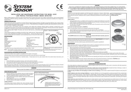
Installation And Maintenance Instructions For Model 2351e Low Profile Photoelectronic Smoke Detector Manualzz

2351e System Sensor Europe Manualzz

Installation And Maintenance Instructions For Model 2351e Low Manualzz
I56 1718 011 2351e A Manual Cpd Pmd System Sensor Canada
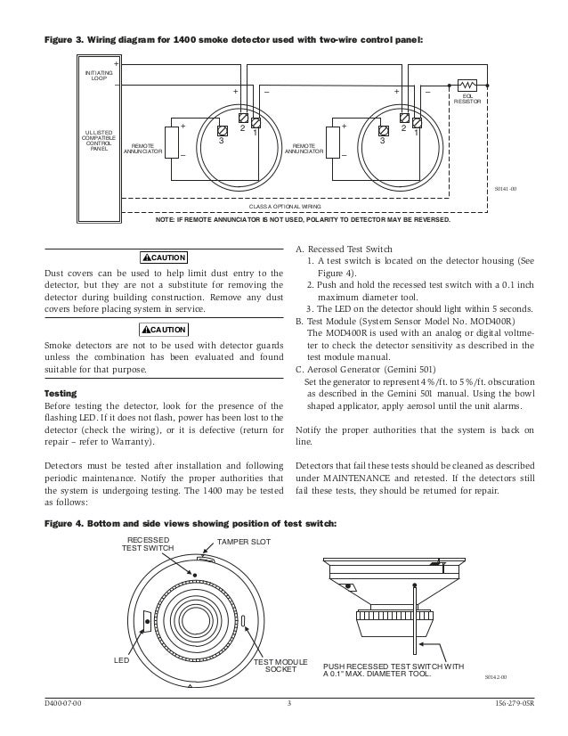
System Sensor 1400 Manual I56 0279
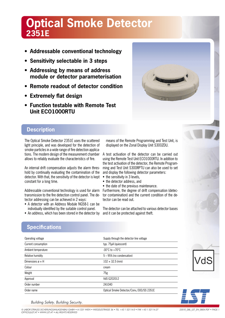
Lst 2351e User S Manual Manualzz
An initial appearance at a circuit representation could be confusing however if you could read a metro map you could read schematics.
System sensor 2351e smoke detector wiring diagram.

C O N V E N T I O N A L Manualzz
System Sensor 2351e Conventional Smoke Detector Rybb Fire Alarm
Descargar Manualzz
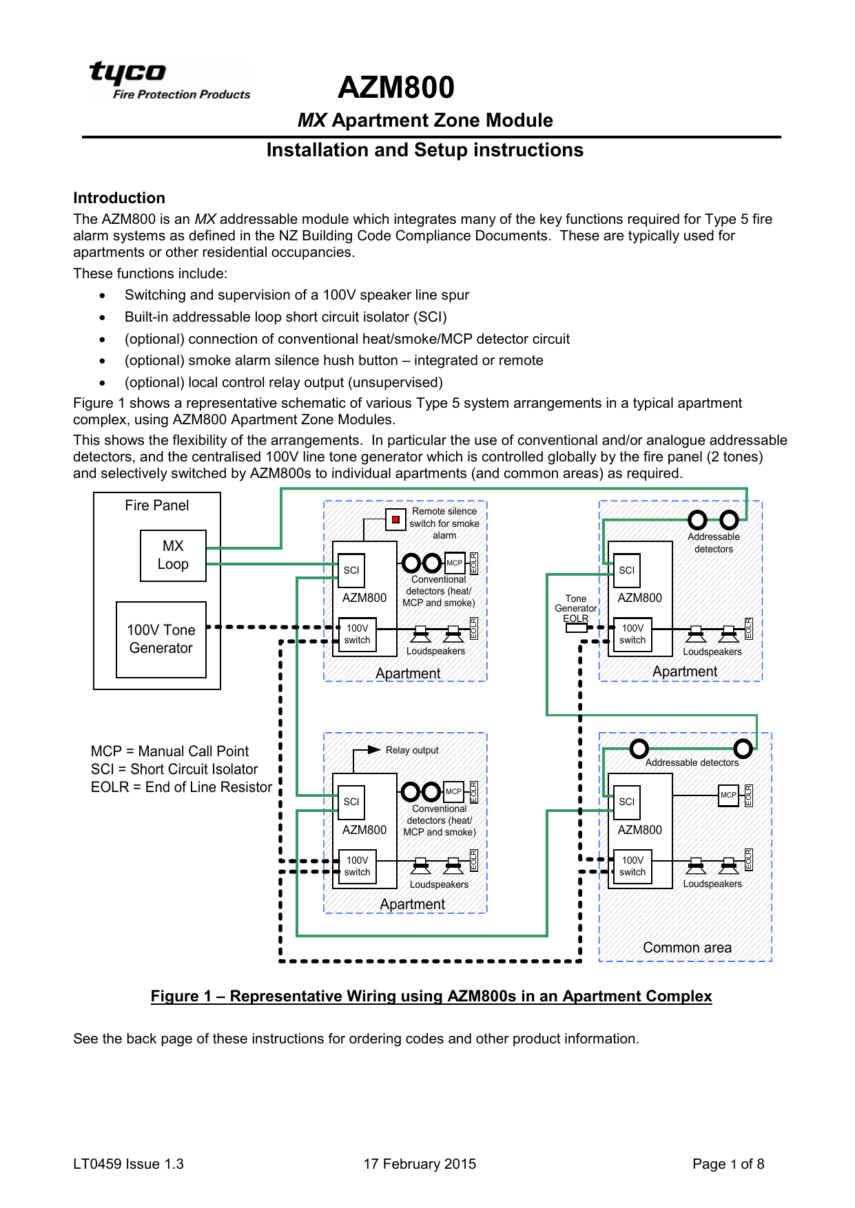
Lt0459 Azm800 Apartment Zone Module Installation And Setup Manualzz
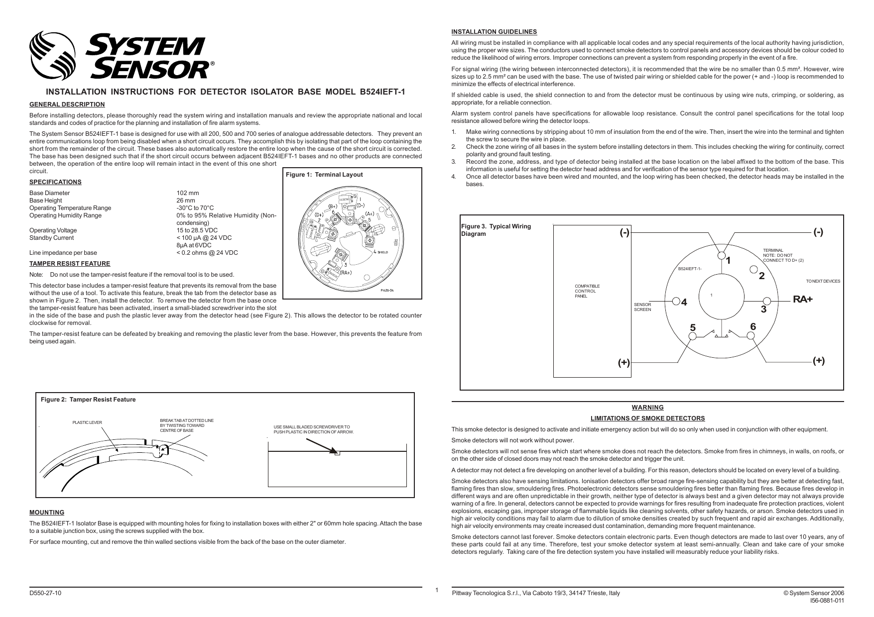
I56 0881 011 B524ieft Manualzz
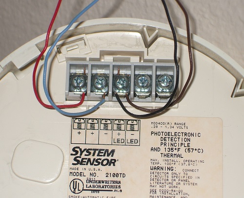
Connecting 2 Wire Smoke Detectors

Ew 3368 System Sensor Smoke Detector Wiring Diagram Free Diagram

Page 1 C 2006 Version 2 1 January 2006 55370058 1500 Series Manualzz
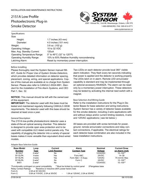
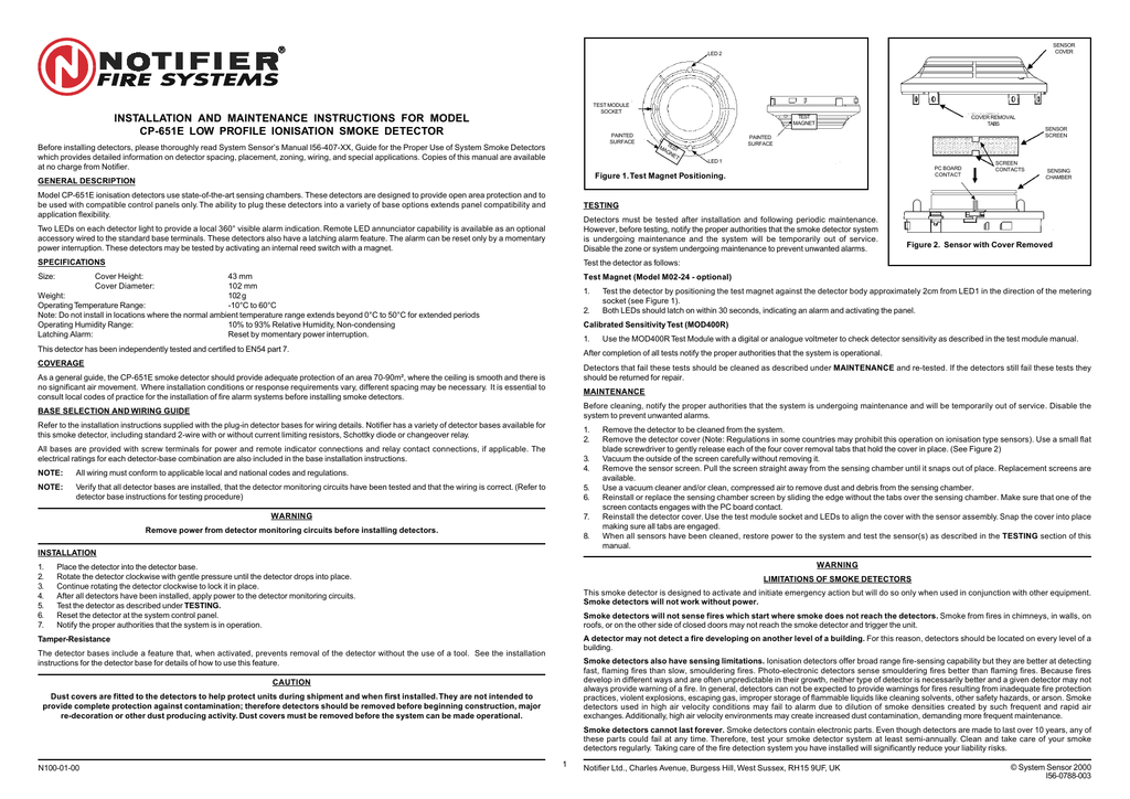
2151a Low Profile Photoelectronic Plug In Smoke Detector

System Sensor Fsb 200 Installation And Maintenance Instructions Manual Pdf Download Manualslib

Lst Nd2251em User S Manual Manualzz
Installation Instructions System Sensor Canada
1412a And 1424a Direct Wire Ionization Smoke Detectors

System Sensor 2351e Conventional Optical Photo Smoke Detector Ebay

Series 300 Conventional Relay Bases F Manualzz
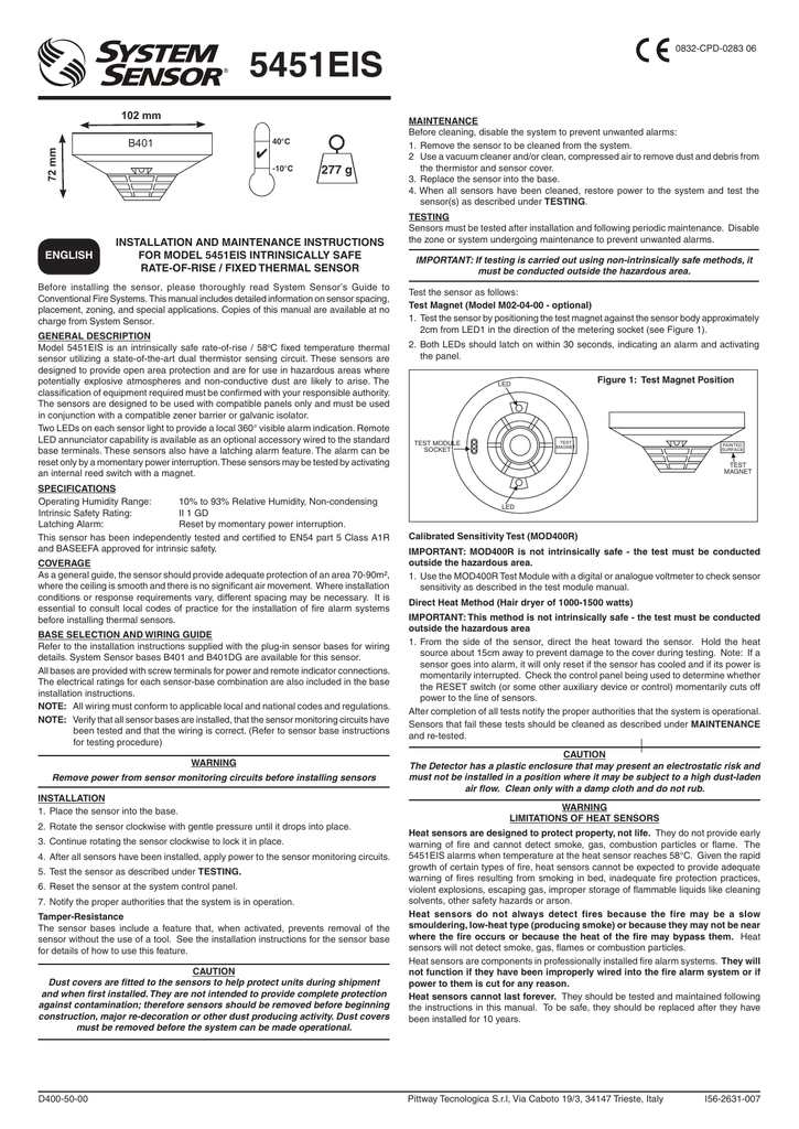
5451eis System Sensor Europe Manualzz
Installation Instructions System Sensor Canada
Part 1 Section 3

System Sensor Plastic Smoke Detector Sensor Pack Of 2 Amazon In Home Improvement
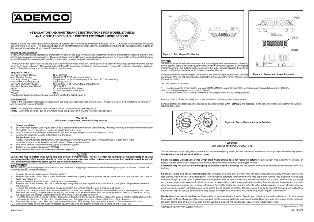
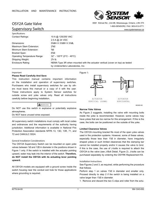
Installation And Maintenance Instructions For Model 2700ecm Manualzz

Conventional S300 Photoelectric Smoke Detector En

List Of Certificates Of The Bosec Brand Liste Des Certificats De Manualzz

2 Wire Photoelectric Duct Smoke Detector System Sensor Canada

Tyco Safety Products Fire Detection New Zealand Product Catalogue Issue 1 Pdf Free Download
Source : pinterest.com
