Testing Door Lock Solenoid
Door Lock Actuator Problems Testing Replacement

Discover How To Test A Door Lock Actuator On Your Car Or Suv Learn How It Works Youtube
How To Test Computer Controlled Door Locks Subaru Youtube

Banggood Testing 12v Electronic Door Lock Youtube
Door Lock Actuator Diagnosis And Repair
How To Repair A Door Lock Actuator Yourmechanic Advice

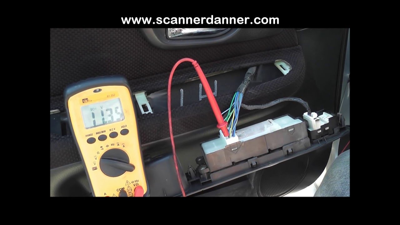
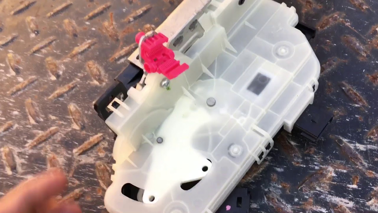
You should see the voltage polarity toggle with each switch activation.
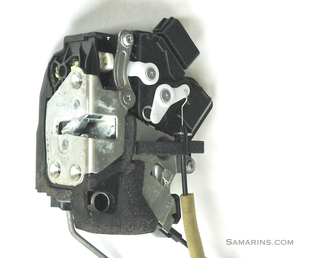
Testing door lock solenoid.

How To Test Frigidaire Door Lock Part 131763256 131763202 Youtube

Testing Whirlpool Duet Door Lock Latch Hook Switch Assembly
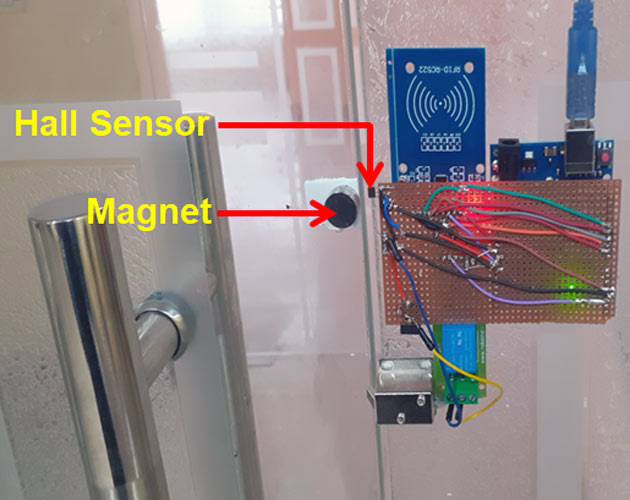
Arduino Solenoid Door Lock Using Rfid

How To Repair A Door Lock Actuator Motor Low Cost Way Youtube

Exterior Door Handle Not Working Door Lock Actuator 5th Gen 4runner

Oe Solutions Integrated Door Lock Actuator 931 121 The Home Depot
Wiring A Spdt Relay With Harness Online Technical Support

How To Fix Power Door Lock Actuator Toyota Lexus Diy Youtube

How To Test Door Lock Actuator On Mazda Door Does Not Lock Unlock Test Youtube

Ford Mondeo Mark 3 Boot Lock And Solenoid Test Youtube
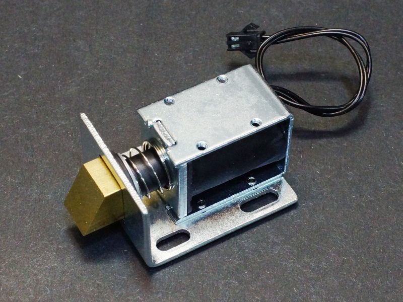
Solenoid Electric Door Lock 12v 1 7a 1kg Pull Protosupplies
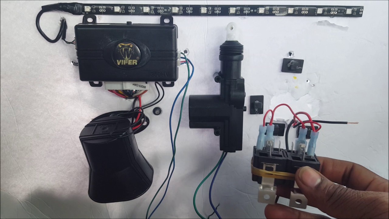
How To Wire Up A 5 Wire Door Lock Actuator Relay From Start To Finish Very Easy Youtube

How To Replace Door Lock Actuator 88 00 Gmc K1500 Youtube

Oe Solutions Door Lock Actuator Front Left 746 303 Door Locks Honda Cr Car Accessories For Girls

Door Lock Actuator Motor Front Right Dorman 931 121 Buick Lucerne Chevrolet Cobalt Actuator

W123 Door Lock Actuator Diaphragm Page 2 Peachparts Mercedes Benz Forum

Oe Solutions Door Lock Actuator Integrated With Latch 931 636 Dodge Ram Crew Cab Door Locks Door Latch
Oe Solutions Integrated Door Lock Actuator Door Locks 2004 Toyota Tacoma Bmw
Https Encrypted Tbn0 Gstatic Com Images Q Tbn 3aand9gcte94x86dcy8xqkt Ealab4dkcfxqdwsf0 Qjobz6yyzhbeyf5e Usqp Cau
2009 2014 Ford F 150 Door Lock Actuator Latch Replacement How To Youtube

Oe Solutions Integrated Door Lock Actuator 931 186 The Home Depot In 2020 Actuator Door Locks Dorman
Atf8000fe1 Door Lock Assembly Resistance Question Applianceblog Repair Forums

Oe Solutions Liftgate Lock Actuator 746 015 Premium Cars Door Locks Electric Motor

2004 Honda Accord Door Lock Actuator With Diagnostic Youtube
Source : pinterest.com
